Gathering SFM MVS Data for Processing and Generation of a 3d Model using Pix4D
- Josh Grobart
- Nov 1, 2021
- 2 min read

Updated: Dec 8, 2021
Introduction
For this lab my partner and I were assigned to fly a double grid mission. The mission we were assigned to fly required us to fly without camera set Nadir, so we had a straight down view. Flying conditions were not idea at all with winds gusting to 25 knots but the Mavic held up. Cloud coverage was minimal with few clouds and mostly otherwise blue sky. Regarding any potential hazards, we identified several light posts, so we made sure to fly to an altitude higher than the posts so that risk was mitigated. Based off of the assigned camera settings used for the mission I was not confident in regards to how well our 3d model would turn out after the data processing as flying with a straight down Birdseye view camera angle does not allow for any of the subjects edges to be captured properly from proper angles.
Methods
Using a Mavic 2 Pro along with Measure Ground Control I was able to pre-program a flight route for the drone to follow. With the mission setting discussed above in the introduction, the mission was flown autonomously. For data processing, Pix4D was used to render a 3d model representing the collected data from the mission.
Discussion
I would not recommend only using a Nadir angel flying directly overhead when trying to create a 3d model of a budling such as that used in this lab. By Soley relying on the Birdseye view if you will the data captured was limited in terms of being able to capture much depth and details of the shed at all. This however is something that should be expected when flying an overhead crosshatch pattern with the camera set to straight down as you are only getting an overhead view hence not allowing for any variety of angles to be captured and any depth to be present. However, it is important to keep in mind that flying a similar mission but of a much larger building, these types of mission parameters could be useful when working in a swarm and then meshing projects together.
Photos and further Discussion

Figure 1: Map view of all the data points
Based on the processing no errors were reported so all captured data points had proper gps tagging. Based on the map view of all the data points collected one area of concern that could be addressed for future operations is making sure that sufficient data points have been collected. As seen above the number of data points showed in Figure 1 is not ideal of 3d model processing and needs more data for a more accurate 3d model to be created.
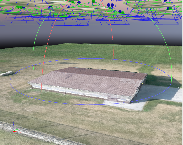
Figure 2: Final product of the 3d model.
As you can see in Figure 2 the model is very shallow and lacks really any depth. This goes back to my original prediction of how the model would turn out based on the camera settings and parameters used to collect data for this mission.


Comments